Turbine control system Suppression schematic gaseous nozzle extinguishing energies Fire sprinkler system element and classification of installation area diagram a turbine/turboprop fire protection system
[DIAGRAM] Wiring Diagrams For Aircraft Generators - MYDIAGRAM.ONLINE
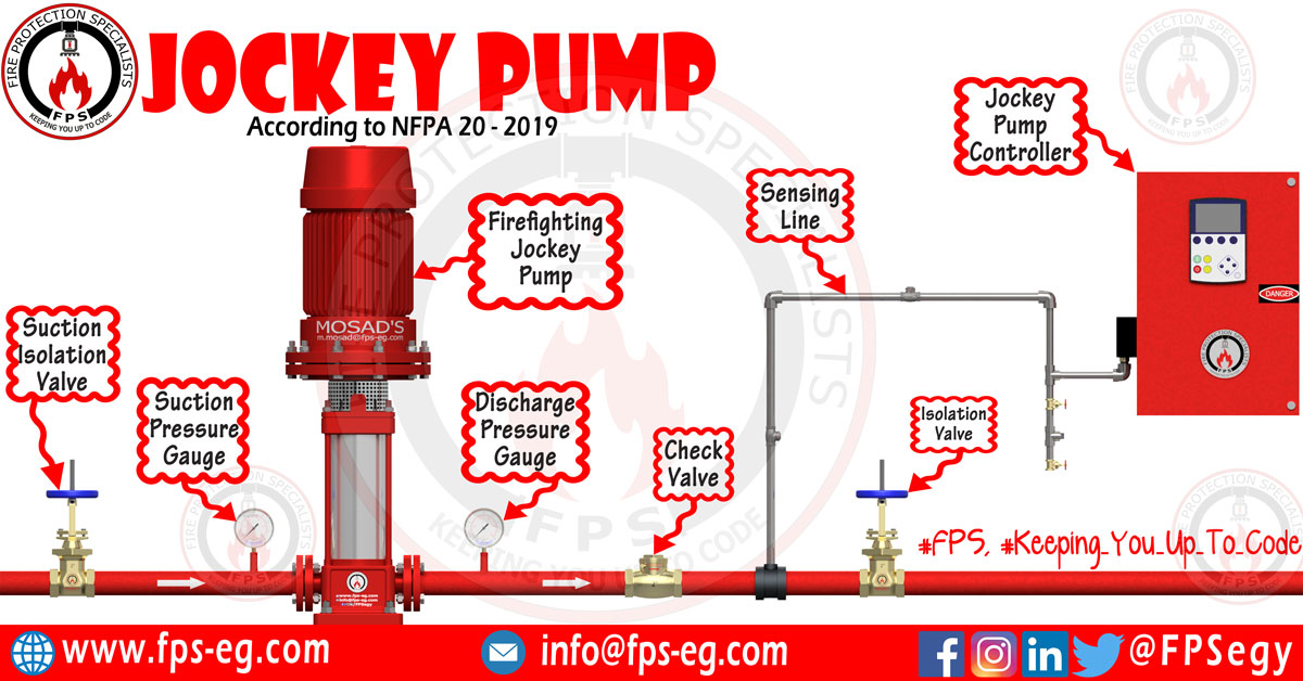
Jockey pump requirements & sizing Turbine control system Pump fire system sprinkler hydrant control panel save
Fire protection of turbines
Free-turbine turboshaft schematics. from wikipedia 3[diagram] addressable fire alarm system diagrams Sprinkler fire system protection alarm firefighting pipe suppression hvac office sg sch spr sprinklers systems safety fm gas generatedProtection diagrams installation sprinkler electricaltechnology loops.
Fire sprinkler system, fire fighting pump accessories, mumbai, indiaFire sprinkler system, fire protection system, fire alarm system The diagram of the turbine control system in the case of fault of theTurbine engine aircraft diagram.

Fire alarm system circuit diagram
Aircraft engine fire protection system ~ part 66 preparationTypes of fire alarm systems and their wiring diagrams Fixed-shaft turboprop engineTurboprop engine.
11+ class a fire alarm wiring diagram imagesTurbine protection system Types of fire alarm systems and their wiring diagramsSchematic diagram of the gaseous fire-suppression system..
Fire pump fire sprinkler system fire hydrant, png, 800x473px, fire pump
[diagram] wiring diagrams for aircraft generatorsSchematic diagram showing the operation of a turboprop engine [28 Fire protection for power generationGas turbine engine fire protection.
Aircraft systems: engine fire detection systems and fire zones️fire alarm installation wiring diagram free download| gmbar.co Turbine protection systemSprinkler fighting pump typical.
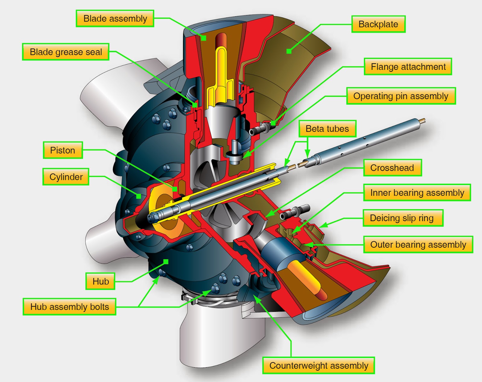
Turboshaft engine diagram
.
.


![[DIAGRAM] Wiring Diagrams For Aircraft Generators - MYDIAGRAM.ONLINE](https://i2.wp.com/i.stack.imgur.com/cCw2d.png)

